

Weather resistance is not a single claim. It is proof from salt spray, damp heat, and extreme cold checks that
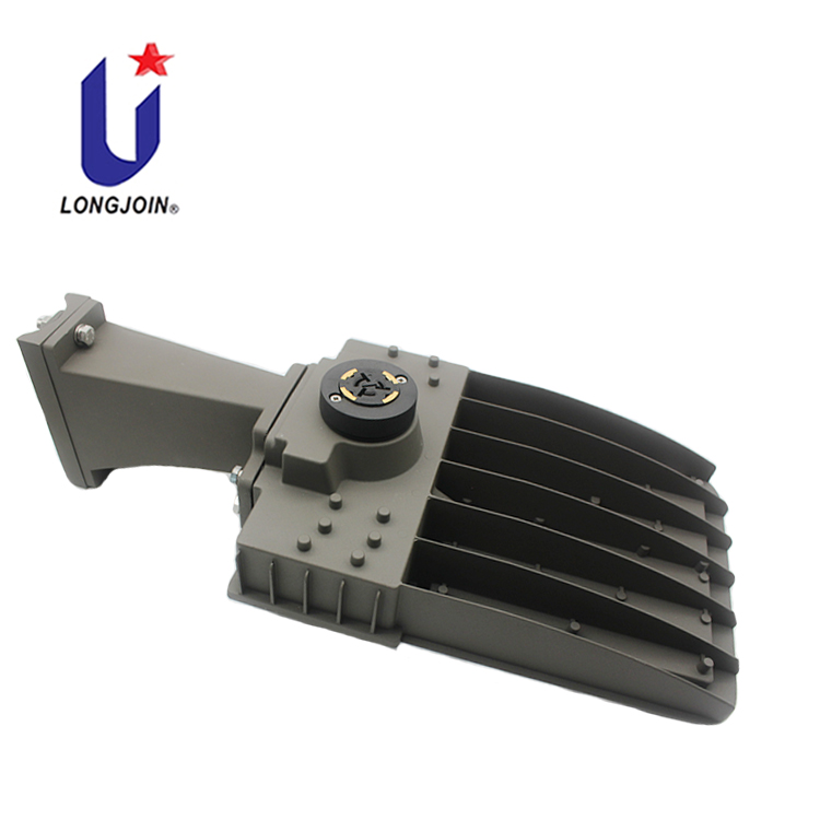
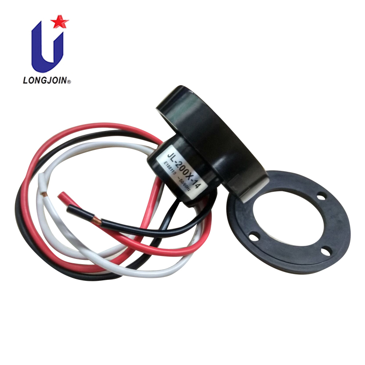
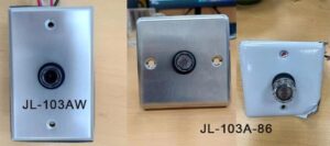
Button photocells work well for smaller direct-wire fixtures. They are easy to install and easy to reach. NEMA photocells work
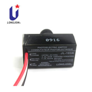
If you need basic dusk-to-dawn control, start with the simplest match: thermal for slow-and-steady, electronic for quick-and-responsive. Then add protection
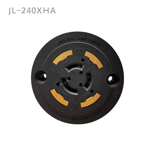
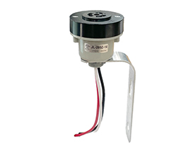
NEMA 3-pin receptacles are the practical choice for simple automatic street lighting. NEMA 7-pin receptacles are built for smart control,