


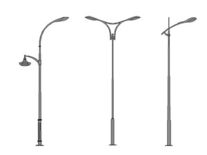


Top mounting and side mounting both work, but only if you match the position to the fixture and the site.
Should twist-lock photocells have a north arrow? For any serious outdoor lighting project, yes.
The arrow solves a real
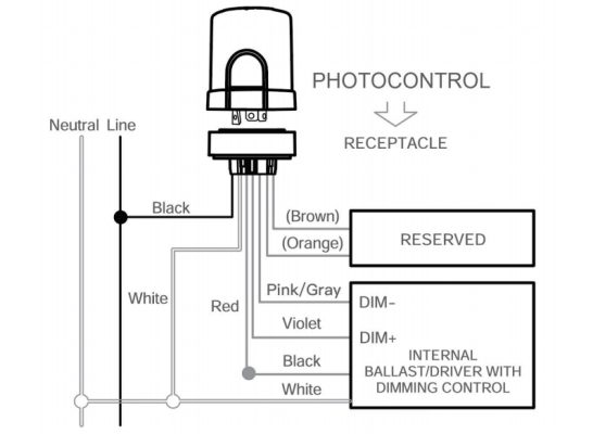
Old lamps were forgiving. LED is not, at least not to the control gear sitting on top of it.
Chiang Rai’s smart lighting market is not looking for basic photocells. It needs wireless control that actually works in difficult