Mastering the Basics: How to Properly Wire 4-Pin Zhaga Interfaces for Outdoor Lighting Control
Introduce
Outdoor lighting control plays an important role in modern urban infrastructures, not only in guaranteeing lighting performance, but also with regard to energy efficiency and system safety. In order to achieve standardised and efficient lighting control systems, the use of Zhaga interfaces has become an industry standard. In order to promote the standardised design and innovative application of lighting equipment, we introduce the JL-700 Zhaga socket and provide a solution with integrated DALI dimming protocol to meet the diverse needs of modern lighting control.
What is the 4 Pin Zhaga Interface?
Developed on the basis of the Zhaga Book 18 standard, the Zhaga socket type JL-700 provides a standardised interface. This compact size not only brings the possibility of more flexible luminaire design, but also features advanced sealing and IP66 protection without mounting screws. It supports Ø40mm photocontrollers and uses the same connectors as Ø80mm central management systems with flexible mounting positions (up, down and sideways). The unique one-piece gasket design significantly reduces assembly time.
The JL-700 Zhaga Socket version has the following interface details:
– Port 1 (brown): 24V DC
– Port 2 (grey): DALI protocol – or access to common ground
– Port 3 (blue): access to DALI protocol positive line
– Port 4 (black): general purpose input/output port
Here is how these pins function.
– Pin 1 (Power Supply): Provides the voltage to power the control module.
– Pin 2 (Ground): Completes the electrical circuit. It acts as a reference point for voltage.
– Pin 3 & 4 (Data Lines): It is used for communication between the control module and the luminaire.
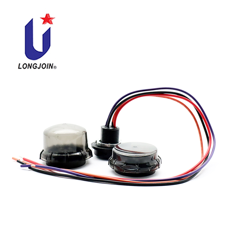
Caption: Zhaga type Socket
Step-by-step wiring procedure:
Proper wiring of the 4-pin Zhaga interface for outdoor lighting control requires careful attention to the following steps:
Step 1: Preparation
Follow the manufacturer’s guidelines and installation recommendations to ensure compatibility between all components and to match voltage ratings. Set out all necessary tools for quick access when wiring.
Step 2: Identify pins and connections
Clearly identify the function of each pin on the Zhaga interface. Generally the pins will be labelled or you can refer to the manufacturer’s documentation to determine this.
Attach the wires to the corresponding pins on the Zhaga interface.
– Pin 1: Connect the positive wire from the power supply.
– Pin 2: Connect the ground wire.
– Pin 3: Connect the D+ wire for data.
– Pin 4: Connect the D-wire for data.
Use a crimping tool or soldering iron to secure the connections. They should be tight and free of loose strands as it can cause shorts. Double-check each connection for tightness. Loose connections result in failures.
Step 3: Wiring Process
Using a tool, carefully remove approximately 6mm of insulation from the end of the wire, making sure not to damage the conductors. Ensure that the ends of the wires are clean and that the metal parts are exposed to make the connections. Use pliers or a soldering tool to connect the wires to the correct pins.
Caption: Zhaga Socket with DALI
Step 4: Test Connections
You have to Verify the working of the wiring before finalizing the installation. For this, you need a multimeter. Set your multimeter to measure continuity. Check each connection for a continuous path. Measure the voltage at Pin 1. It should match the power supply’s output (typically 24V DC).
Check that there is no unintended connection between the pins. Connect the multimeter in series with the circuit to measure the current. The current should always be in an acceptable range for your components.
Step 5: Insulate Wires
You have to protect the connections from environmental factors and mechanical stress. Use heat shrink tubing over each connection. Slide the tubing over the connection. You can use a heat gun to shrink it in place. It creates a secure connection. Wrap electrical tape around any exposed areas to provide extra insulation and protection.
You can also Organize the wires using cable ties or clips. Secure them to the mounting surface or within the luminaire housing. It prevents movement and reduces the risk of damage.
Step 6: Weatherproofing
To protect the entire Zhaga interface and connection points, place them in an outdoor waterproof rated interface box, such as IP66 or IP67, to ensure that the interface is isolated from environmental factors.
Wrapping it Up!
The correct installation of Zhaga interfaces is essential for the safety and long-term use of your outdoor lighting system. By following the steps outlined above, we were able to ensure that the system was installed in accordance with industry standards while reducing maintenance costs. By choosing the Model JL-700 Zhaga receptacle, your outdoor lighting control system will be more reliable and long lasting.
https://rainfordsolutions.com/resources/faqs/ip-ratings-and-standards-explained/#:~:text=The%20IP%20rating%20or%20IP,BS%20EN%2060529%3A1992
Tips:
To wire the 4-pin Zhaga connector, you will need a few tools. Below is a brief list;
Essential Tools
- Wire strippers: Used to remove the insulation from the ends of the wires without damaging them.
- Screwdriver: various sizes and types for fixing connectors and terminals.
- Multimeter: for measuring voltage and current to ensure proper electrical connections.
- Crimping tool: Used to securely attach connectors to the end of wires.
- Heat Gun: Used to insulate and protect connections using heat shrink tubing.
Recommended Materials
- Quality Wire: Use the proper gauge and type of wire for outdoor environments.
- connectors and terminals: High-quality terminals that meet Zhaga interface specifications.
- insulating materials Heat shrink tubing and electrical tape to insulate connections and prevent short circuits.
- cable ties and clips to secure wires and prevent them from becoming tangled or damaged.

External Link
https://rainfordsolutions.com/resources/faqs/ip-ratings-and-standards-explained/#:~:text=The%20IP%20rating%20or%20IP,BS%20EN%2060529%3A1992


